Wednesday, June 29, 2016

Vivado HLS from ROM

This link breaks down how to read in a csv (or other data file type) and gives instructions about how to convert each of the files to header files that can be synthesized by the HLS tool. The problem is, if this is all done by the Zedboard, it would mean that converting to a header file from a csv would have to be executed one by one because the function to do so includes fopen, fscanf, and fclose (which cannot be synthesized by hls because they are too high level.

https://forums.xilinx.com/t5/High-Level-Synthesis-HLS/HLS-ROM-from-file/td-p/654517

So from digging the answer might be in one of many places but for now my ideas are the following:


  1. Place the function that will convert the csv to a header file in the testbench function in HLS. 
    1. This function will create the header file that can be read by the "to be synthesized source file" in HLS. The pre-filter, pass1, and pass2 can all be pipelined from there although I doubt that will speed up the process at all. If the idea is to process in parallel, then the part we want to pipeline would be the conversion (more files at once)
    2. Of course one would have to look at the time it takes to receive one sample data set (that 2x502) file that comes from the scope (I will learn later this week or next how exactly this is done and have a better idea of what direction to go). If the time it takes to create one pulse is similar to the time it takes to convert that data into a header file that can be read by HLS code, then we are in good shape because the processor will be able to keep up with the incoming data. However, if the data coming in exceeds the speed of the testbench conversion into a header file then we are in trouble, and this would seem like a good place to begin parallel processing but we are again met with the problem of fopen, fscanf, and fclose not being able to be synthesized. 
      1. So I plan on figuring out the times for each of these processes and figuring out what the best course of action is. The fear is that the data will come in much quicker thatn the processor can process, and we will be in trouble...............BUT that's why I'm thinking of other ways to solve this problem from the beginning!
  2. Extract the fopen, fscanf, and fclose functions from the stdio.h library and see if the lower level code that creates those functions can be synthesized.
    1. It would seem as though, at some level, the code HAS to be able to be synthesized, but you know, nothing ever works correctly, so there could be a third option on this blog by next week. 

Friday, June 17, 2016

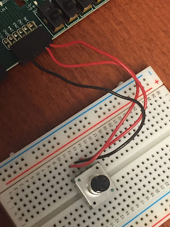
Digilent PmodENC

The Digilent Rotary Encoder Module

This Pmod features a rotary shaft encoder with an integral push button. It also includes a sliding switch that is commonly used as an on/off output.

A rotary encoder is most commonly used to detect how many "clicks" a knob has been rotated. This is the number in GTKterm labeled 'Encoder Value' and underneath that it records the angle.


We also created a knob for the top of the rotary shaft in order to increase stability and accuracy when rotating.


Initially we were hoping that we would be able to use the exact code and process that we use in Emily's previous blog 'Angle Encoder' but unfortunately we came across some problems. We were able to complete all of the steps successfully, however, we had some issues with the outputs. For example, when using the ALPHA encoder we were easily able to recognize a pattern within each click of the LEDs but with the new encoder we were unable to find any sort of pattern at all. The LEDs seemed to be lighting in a random fashion and the Encoder Value was not counting consecutively like it should be. Instead, it would repeat numbers several times and jump around. 

We checked the Pmod connections to the ZedBoard, which were correct so we know that is not the problem and we also checked to make sure it was receiving power. We measured the output to be about 3.3 volts so that is also not where the issue lies. At this point we think that the problem is most likely somewhere within the code.

If we had some more time we would try these options provided to us by Mike:

1. Disconnect the encoder from the PMOD and hook it up to a breadboard. Then use wires to connect back to the PMOD appropriately. I have a feeling that the way the encoder is set up, it has the encoder pins opposite of the ones we are used to. So essentially, the output pins from the encoder would have to be switched (using wires) to connect to JA1 and JA2. 

2. Leaving the encoder attached to the PMOD, change which input is the MSB. I mean that somewhere in the code, in the interrupt function, you are reading from both encoder pins, then combining the two read values into one. If it says MSB >> LSB, change it to LSB >> MSB. I do not remember the exact structure of the code off the top of my head, so you'll have to do some messing around.

3. If both above options fail, and you really want this thing to work before you leave tomorrow, get a multimeter out, hook up power to the power pin of the encoder, and see what each encoder pin is spitting out as you rotate the shaft. If it is a different readout then what you get from the other encoders, then you'll have to do some restructuring of the code to get the encoderValue to change when it is supposed to.

4. BEFORE YOU TRY ANY OF THESE THOUGH, make sure the design is working correctly with the other encoders. This will eliminate a lot of troubleshooting because the issue could lie with the PMOD rather than the enocders or the software.*-+


Helpful Links:
https://reference.digilentinc.com/_media/pmod:pmod:pmodENC_rm.pdf


To Be Continued...

Wednesday, June 15, 2016

Digilent Pmod ADC

The new Digilent Pmod ADC1 has arrived!

Useful Links:
http://store.digilentinc.com/pmodad1-two-12-bit-a-d-inputs/
https://reference.digilentinc.com/_media/pmod:pmod:pmodAD1_rm.pdf
https://reference.digilentinc.com/_media/pmod:pmod:pmodAD1_sch.pdf

When connecting the Analog Discovery to the chip, refer to the following link:
https://reference.digilentinc.com/_media/analog_discovery:analog_discovery_pinout.pdf

The datasheet for the Pmod explains that the external power provided to the chip must be within 2.35 to 5.25 volts.

Note: The sampling rate is 1 million samples per second and  will provide 12 bits of information through 16 clock cycles.

The issue of testing this chip is the software. It appears that the pins of both the Maxim ADC and the Digilent ADC are the same so the hardware and the pmod interface should be the same as well. However, the maxim code only recognizes the maxim chips and the code on the blog from last summer that allowed us to read in a code using a function generator and the Max11205 does not work either. It is possible that there is an error in the code because the computer crashed the last day and it is possible that the final code was not saved.

Friday, June 10, 2016

Angle Encoder


The first thing we want to do is clone the repository:
1. Create a new folder in zynquser where you want to store your new files: zynquser > Angle_Encoder
2. In the terminal, type sudo yum install git in order to install github.
3. Find the directory where you want your files to be save: cd Angle_Encoder
4. In this file, type git clone https://github.com/mf06engl/Angle_Encoder
This clones the files that Mike posted on github into the folder you created.


5. Open Vivado > Open Project > zynquser > Angle_Encoder > Angle_Encoder > Encoder Hardware > Encoder_Hardware.xpr
(Automatically upgrade to current version if need be).
6. If your IP blocks need to be upgraded, click the Show IP Status button near the top of the page, select all the blocks and upgrade them. If there are any warnings click OK.
7. Run synthesis and run implementation.
8. Generate the bitstream.
9. File > Export > Export Hardware to Local Project (include bitstream). If a warning comes up asking if you would like to overwrite a previously made hardware click YES.
10. File > Launch SDK.


Once you open SDK, you should see the application project, board support package, and the hardware platform.
The software code should be located under Encoder Software > src


Next, we need to make sure GTKterm is open in order to read the values that we read from the encoder. 

1. In the terminal, make sure GTKterm is downloaded. If not, go to  http://dl.fedoraproject.org/pub/epel/6/i386/ and search for  epel-release-6-8.noarch.rpm.
2.  Once you locate the previous link, download and install the application. 
3. In the terminal, type sudo yum install gtkterm.
4. Then type the following: 
                       cd ..
                       cd ..
                       cd dev (in zynquser)
                       ls -l ttyACM0
   If the permission are denied (it does not show crw-rw-rw) then type:  
                       sudo chmod 666 ttyACM0


 To connect the angle encoder, we need to use a breadboard and connect wires from the encoder to the pin outs on the PMOD. Using the previous blog post from Sam, 'Connecting the ALPHA Angle Encoder to the Zedboard,' we can see exactly how it's connected. We use pins JA1 and JA2 connected to Prong 1 and 3 respectively while the 2nd Prong is connected to ground.  

Once everything is properly connected to the Zedboard, we can program the Zedboard in SDK and launch the hardware to the board. 

In the GTKterm we can see that it reads an Encoder Value as well as the value of the Angle. We can conclude that each turn either increases or decreases by 7.5 degrees, depending on whether it is turning clockwise or counterclockwise. Each click of a turn on the angle encoder is equivalent to 4 values, so in order to read each single value you must turn the encoder very slowly and carefully.  The Angle Encoder value is the number of clicks that it has turned from its starting position, which should be zero. When it turns clockwise, this value is negative, and when it turns counterclockwise this value is positive.

The values are shown by the lighting of the LEDs, which only light 4 at a time, having the first 2 bits reading the outputs of Pin 1 and Pin 2 respectively, and the 3rd and 4th bits act as place holders. It acts through a process called 'bit shifting,' where it will read the values through Pin 1 and Pin 2 and then for the next turn it will move the previous measurement to the place holder and read another set of values. 

For example, let's say the four bits are numbered 4  3  2  1  , and the first read measurement is 01. The 01 would be placed in spots 2 and 1 and would look like the following: 
0  0  0  1 .  If the next read value is 11, the previous measurement (01) would be shifted from spots 2 and 1 and into spots 4 and 3, while the current measurement replaces it in spots 2 and 1. That would look like the following:  0  1  1  1 . This pattern would continue with every new read value.  

When it is turned clockwise, the LEDs rotate in the following rotation:
                                0 1 1 1 
                                1 1 1 0
                                1 0 0 0 
                                0 0 0 1
 When it is turned counterclockwise, the LED's 
                                1 0 1
                                1 1 0 1
                                0 1 0 0
                                0 0 1 0 


Part 1: The following video is of the angle encoder being rotated counterclockwise

https://www.youtube.com/watch?v=quktJql8WBI


Part 2: The following video is of the angle encoder being rotated clockwise.

https://www.youtube.com/watch?v=kSy4wF8xKa8&spfreload=5


Thursday, June 9, 2016

Connecting the ALPHA Angle Encoder to the ZedBoard

When trying to connect an angle encoder to a ZedBoard it can become confusing because when searching the internet, you can really only find examples of an angle encoder connected to an Arduino. However, after some research and sessions of trial and error, we were able to determine a successful connection option.


When looking a the encoder, ALPHA should be listed at the top. The side that has three prongs is where we are going to be working. The three prongs at the bottom we will refer to as Prong 1-3, going from left to right. Prongs 1 and 3 are inputs and Prong 2 is ground.

An example of the specific connections we made when using the angle encoder are, Prong 1 connected to JA1, Prong 2 connected to ground and Prong 3 connected to JA2 (These specific connections JA1 and JA2 may vary depending on the code you are using). We were successful with these connections to the ZedBoard which can be further read about in Emily's Post titled, Angle Encoder.


Helpful Link:
http://bildr.org/2012/08/rotary-encoder-arduino/

Wednesday, June 8, 2016

Waveform generator outputs

Using the following setup where the yellow wire is the waveform generator and is connected to Vin of the max11205 chip, and the black wire is ground.

The waveform generator is sending a constant signal of 3.6 volts. The output is 32767 decimal.

However, I noticed that the value for the decimal  is the same for signals above 2.5 V. After looking at the datasheet (highlighted below), it is possible that the 2.5V is the maximum voltage for the chip. 


Then the following outputs would make sense.

2.5 V    ->        32767
1.25  V      ->           16489
0.625 V       ->            8323
0        ->           160

I don't understand why zero volts outputs 160 but if you add this value to the rest of the outputs, as you go down the list which is taking half of the previous voltage, then the output is halved as well. 

This is also why the following line of code from menu.c includes the number 2500mV:

printf("%d of %d samples = %d decimal.  (%d mV)\r\n",i+1,unNumberSamplesToCapture,nAdcValue,((nAdcValue * 2500)/32768));

This is just converting the read bit value to a voltage in mV. This is done by simply multiplying by 2500mV and dividing by 32768 just as you would when solving a proportion.


Tuesday, June 7, 2016

Using the Analog Discovery Box and the ADC


The picture above shows how to connect the Analog Discovery Portable Analog Circuit Design Kit to the ADC Maxim chip. The black wire is ground and the yellow wire is the wave generator.

The wave generated is just a constant signal of 3.6 V shown in the picture below.


This is the output when using the 3.6 V. This makes sense because the max voltage that the maxim chip can take is 3.6 V so this should result in the max value of the 15 bit number which is 32767. I am confused on why it wouldn't be the max value of a 16 bit number but I have to look into this some more. 


When a signal of 1.8 V was created using the wave generator, the output was 14971, which behaved almost like I expected. When I took half of the wave voltage, the output was almost halved. I will also have to look into the relationship between these values.

Petalinux commands not found, errors

After a fresh install of Petalinux v2016.1 via the installer (http://www.xilinx.com/support/download/index.html/content/xilinx/en/downloadNav/embedded-design-tools/2015-4.html)

Make the file executable by typing in the terminal in the directory of the installer download: 'sudo chmod +x filename.run'. Then, begin the install by typing: './filename.run' (where filename.run is the actual name of the file downloaded. For me it was petalinux-v2016.1-final-installer.run).

If the install requires additional tools and packages to properly download, download them. How to do this can be found online pretty easily.

After the install is complete, you may experience errors that may tell you certain commands are not found when you try and execute them. To avoid this inconvenience, in the terminal type:

IMPORTANT NOTE - YOU MUST RUN THE SETTINGS SCRIPT EACH TIME YOU OPEN A NEW TERMINAL OR SHELL. THE PETALINUX TOOLS WILL FAIL OTHERWISE.

'source <path to installation of petalinux>/ settings.sh'
'echo $PETALINUX'
'/opt/Xilinx/petalinux-v201X.x-final'


So for example in my circumstance I executed:

'source /opt/Xilinx/petalinux-v2016.1-final/ settings.sh'
'echo $PETALINUX'
'/opt/Xilinx/petalinux-v2016.1-final'

Now commands such as create and others should work fine.

Reference the full Petalinux Tools user guide below:

http://www.xilinx.com/support/documentation/sw_manuals/petalinux2014_2/ug977-petalinux-getting-started.pdf

Monday, June 6, 2016

Link to clone SD Cards (for copying linux images)

https://wiki.archlinux.org/index.php/disk_cloning

'Things we should all know' tutorial

Today I completed Mike's Tutorials on the blog titled, Things We should All Know (Vivado HLS) (Vivado) and (Petalinux). 

Once the tutorial is complete and you type in username root and password root, you are then able to control parts of the Zedboard using the terminal. For example, if you navigate to bin and type ls, you will see all the different commands like poke. Then, in Vivado, open the block design and observe that the LEDs are connected to axi_gpio_0. Then click on the Address Editor tab and find this cell. Notice that the offset Address is 0x4120_0000 which is the address that the LEDs are connected to within the Zedboard. 

Then you can go back to the terminal and type the following:
poke 0x4120000 0xFF 
which successfully turned on the LEDs on the Zedboard. Then if you type:
poke 0x4120000 0x0
then the LEDs turn off.


To run Pre_Filter and actually get an output at this point, follow the steps below.

Go through the usual steps of making the block design and then launch SDK. Continue as you would normally and open new application, then import src (Pre_Filter.c) and program the FPGA. Then once you run the program, open up a terminal in the virtual machine and navigate to the directory that contains the .c file. Then type:

make Pre_Filter  (which makes the file an  executable program)
./Pre_Filter     (This actually runs the code)

The output looks like this..

Inline image 1

Proximity Sensor - Maxim44000

Steps to getting the Maxim chip working:

Follow the steps given in the tutorial link below.

This starts with sdk rather than vivado because it includes a hidden block design/code for each of the maxim chips. Once you have completed the tutorial and the FPGA is programmed, then you can use gtk term to read the output of the chip. The instructions below are for installing and using gtk term.

 The following link gives a three step process on how to install gtkterm.
http://pkgs.org/centos-6/epel-i386/gtkterm-0.99.5-11.el6.i686.rpm.html

In the first step, this link is provided:
http://dl.fedoraproject.org/pub/epel/6/i386/

Open the previous link and look for:
epel-release-6-8.noarch.rpm
Click on this link and it will download. Then in the downloads folder, or at the bottom of your web browser, click the file to install it.
Then go to the terminal and type the following:
sudo yum install gtkterm
Directions to use gtkterm are in Sven's blog:
http://svenand.blogdrive.com/archive/173.html#.VWh9l9jbJ9A

At the beginning of the blog, it talks about permissions. Following these steps can help with that:
To check for the permissions, open a terminal and type:
          cd ..
          cd ..  (to move all the way out)
          cd dev (must be in this directory)
          ls -l ttyAMC0  (checks the permission)
If the permission is not crw-rw-rw, then type:
          sudo chmod 666 ttyACM0

Then we are able to follow the steps in Sven's blog.

Then once you run the program, gtk term should look something like the picture below. This picture should the fluctuations in the Proximity value as I moved my hand closer to the sensor and then farther away and repeating this motion.

Inline image 1

I am still unsure of what these values mean but the datasheet (http://datasheets.maximintegrated.com/en/ds/MAX44000.pdf) states that a photodiode array inside the IC converts light to a current which is then processed into a digital value. I think this digital value is an 8 bit number because 2^8 = 256 and the highest value that was outputted when my hand was directly on top of the sensor was 253. This is just an idea and I need to look into this more.

253  fd    11111101
208  d0    1101000
125  7d    01100001
97    61    01100001

Own LED Program

We made our own hardware and software design in order to have the LEDs light up one by one consecutively. We used the 1st Tutorial as a guide to build the hardware with the processing system and an LED GPIO, and then modified the code to change the way the LEDs lit up.


/********************************************************************************************
*This software file will demonstrate the use of a GPIO (General Purpose Input Output) and the
*connection to a Zynq Processing System in order to carry out some function.
*The relatively simple software application that we have created was designed to control the
*LEDs on the ZedBoard. When working, the LEDs will light up one by one consecutively from one
*end to the other.
*******************************************************************************************/


/* Include Files */
#include "xparameters.h"
#include "xgpio.h"
#include "xstatus.h"
#include "xil_printf.h"


/* Definitions */
#define GPIO_DEVICE_ID  XPAR_AXI_GPIO_0_DEVICE_ID    /* GPIO device that LEDs are connected to */
#define LED 0x01                                    /* Initial LED value - X0000000 */
#define LED_DELAY 10000000                            /* Software delay length */
#define LED_CHANNEL 1                                /* GPIO port for LEDs */
#define printf xil_printf                            /* smaller, optimised printf */

XGpio Gpio;                                            /* GPIO Device driver instance */

int EmilyLEDProject(void)
{

    //volatile int delay;
    int Status;
    int led = LED; /* Hold current LED value. Initialize to LED definition */

        /* GPIO driver initialization */
        Status = XGpio_Initialize(&Gpio, GPIO_DEVICE_ID);
        if (Status != XST_SUCCESS) {
            return XST_FAILURE;
        }

        /*Set the direction for the LEDs to output. */
        XGpio_SetDataDirection(&Gpio, LED_CHANNEL, 0x00);


        led = 0x01;
        int i;
        for (i=1;i<8;i++){
            XGpio_DiscreteWrite(&Gpio,LED_CHANNEL,led);
            delay(LED_DELAY);
            led = (int)(1<<i);
            XGpio_DiscreteWrite(&Gpio,LED_CHANNEL,led);
            delay(LED_DELAY);
        }

        return XST_SUCCESS; /* Should be unreachable */
}

void delay(int nStopValue)
/**
* \brief       Loop for nStopValue iterations to provide a delay.
* \par         Details
*              It is commonly used with the constant 'ABOUT_ONE_SECOND' defined in maximPMOD.h for
*              setting approximate delays
*
* \param[in]   nStopValue    - number of iterations to loop
*
* \retval      None
*/
{
    int i=0;
    int a=0;

    for(i=0;i<nStopValue;i++)
    {
        a=i;
    }
}
/* Main function. */
int main(void){

    int Status;

    /* Execute the LED output. */
    Status = EmilyLEDProject();
    if (Status != XST_SUCCESS) {
        xil_printf("GPIO output to the LEDs failed!\r\n");
    }

    return 0;
}


/////////////////////////////////////////////////////////////////////////////////////////////////////////////////////////////
Most of the code was the same as the 1st Tutorial, but we needed to add the delay function from a previous post in order to properly delay the time after each LED lit up. The delay code we used was taken from Mike's previous blog post, and looked like the following:

void delay(int nStopValue)
/**
* \brief       Loop for nStopValue iterations to provide a delay.
* \par         Details
*              It is commonly used with the constant 'ABOUT_ONE_SECOND' defined in maximPMOD.h for
*              setting approximate delays
*
* \param[in]   nStopValue    - number of iterations to loop
*
* \retval      None
*/
{
    int i=0;
    int a=0;

    for(i=0;i<nStopValue;i++)
    {
        a=i;
    }

This allowed for a pause of about one second after one LED lit up to the time the next one did.

/////////////////////////////////////////////////////////////////////////////////////////////////////////////////////////////////

After this code was successfully working, we decided to modify it to make the LEDs light up 1-8 and then back down 8-1 continuously without stopping.
In order to do this we needed to add another 'for' loop right after the first one telling the LEDs to blink consecutively in reverse order from 8 down to 1. The 'for' loop we made looked like the following:

int j;
        for (j=8;j>-2;j--){
                    XGpio_DiscreteWrite(&Gpio,LED_CHANNEL,led);
                    delay(LED_DELAY);
                    led = (int)(1<<j);
                    //XGpio_DiscreteWrite(&Gpio,LED_CHANNEL,led);
                    delay(LED_DELAY);
                }
}

We named the variable 'j' and made it decrement by 1 starting at LED 8 and going down to -2. We had trouble getting it all the way down to the last LED and it seemed that it was reading the value for the first LED to be -2.


In order to make this non-stop we needed to put both the 2 'for' loops in a 'while' loop, which successfully made it run up the LEDs and back down without stopping.

////////////////////////////////////////////////////////////////////////////////////////////////////////////////////////////////// 


Saturday, June 4, 2016

Adding Files to SD Card to boot Linaro

Now that our SD card is set with a 52 MB FAT 32 boot partition and an ext4 root file system partition, we can add the files that will boot Linaro on the Zedboard.

** What we will need **

- The Out of Box files that come on the SD card with the Zedboard. If you do not have these files, fear not, they can be downloaded from this page : https://reference.digilentinc.com/zedboard:zedboard

Download the Out-of-Box Demo .zip file and extract the files to the directory of your choice

-The Linaro file system from:
http://releases.linaro.org/archive/12.09/ubuntu/precise-images/ubuntu-desktop/linaro-precise-ubuntu-desktop-20120923-436.tar.gz

The file should look like this: linaro-precise-ubuntu-desktop-20120923-436.tar.gz

-Linaro device tree blob file (.dtb) from http://svenand.blogdrive.com/Zynq/Linaro/devicetree_linaro.dtb

The file should look like this: devicetree_linaro.dtb

Once we have all these downloaded, we are ready!

The first step is to copy the image files that come with the Zedboard SD card onto our 52 MB BOOT partition of our SD card. All of these files are located in the sd_image folder of the Zedboard Out of Box Demo download.

Our BOOT partition should look like this.


The next step is to get the Linaro file system onto our SD Card. We want to start by making a directory named 'linaro' in the tmp folder of our computer. This can be done by going to the terminal and typing the following commands.
   
     cd /tmp
     mkdir linaro

Once we have this directory, we should navigate to the folder where our Linaro file system downloaded, and run the following command in the terminal to copy the file to the /tmp/linaro directory that we just created.
     
     sudo cp linaro-precise-ubuntu-desktop-20120923-436.tar.gz /tmp/linaro/

Navigate to the linaro folder by typing cd /tmp/linaro/ in the terminal. Now we are going to unpack the file by running the following command.

     sudo tar zxf  linaro-precise-ubuntu-desktop-20120923-436.tar.gz

Your linaro folder should now look like this.

The next step is to copy the file system to the ext4 rootfs partition of our SD card. You should locate where your partitions are mounted, however they usually get mounted to the /media directory. For my machine, they are mounted at /media/zynquser/. Navigate to /tmp/linaro/binary/boot/filesystem.dir by typing 'cd /tmp/linaro/binary/boot/filesystem.dir' in terminal. Run this command to copy the file system to the rootfs partition of the SD card (This may take a few minutes).

     sudo rsync -a --progress ./ /media/zynquser/rootfs/

Once the above command is complete, unmount the partition to ensure all files have been synchronized successfully. You can unmount the partition in the terminal by typing 'sudo umount /media/zynquser/rootfs/'

We are almost done!

All that is left to do is fix the boot files to correctly boot Linaro. Open the BOOT partition on our SD card, and delete the ramdisk8M.image.gz and devicetree_ramdisk.dtb files. Then, copy the devicetree_linaro.dtb into the BOOT partition. Our BOOT partition should now look like this.


We did it! Our SD card is ready to help us boot Linaro on the Zedboard. To prepare the Zedboard for booting Linaro, please reference this earlier blog entry.

http://zedboardsiena2015.blogspot.com/2016/03/ubuntu-with-linaro-gui-working.html


Preparing SD Card for Linaro to be Booted on Zedboard

According to Sven, (http://svenand.blogdrive.com/archive/199.html) the best way to prepare the SD card for booting Linaro is as follows:

** Things to keep in mind **
- SD Card should have at least 4 GB of free space
- The application gparted can be very useful for correctly partitioning the SD card (I will be using gparted to complete these steps)

Acquire an SD card with at least 4 GB storage available on it (SD card will be wiped clean so back up any files you do not want to lose).

Insert SD card into your computer via a USB converter if you do not have an SD card slot.

Start the gparted application by typing "gparted" into the terminal (sudo may be needed depending on your machine). If you do not have gparted, it can be downloaded by typing "sudo apt-get install gparted" (for Ubuntu users) or "sudo yum install gparted" (for CentOS users).

Locate your device in the gparted user interface. There should be a small drop down arrow in the top right. Your SD card should be in this box, listed below your computers main hard drive. Click on your SD card (It should look something like /dev/sdb/ (memory on your card)). You should now see a screen something like this:

The next steps are to unmount any existing partitions on your card, and then delete them. To unmount your partitions, locate them in the interface (in the picture above, the line that has an ext4 file system and label 'myusb'), right click, and select unmount. Once you have unmounted all partitions, you will delete them (this will DELETE ALL DATA ON THE CARD).

To delete partitions, right click in the same area you did to unmount, and select delete. Your SD card should now be completely free of any partitions, and all the space on the card should be 'unallocated' and you should have a screen like the one below:


Now we will be creating the proper partitions to set up the SD card for booting Linaro.

Right click the line with unallocated file system and select the 'New' option. We want this partition to be 52 MB in size and have a FAT32 file system (Don't forget to leave 4 MB space free preceding the partition). We will name this partition 'BOOT'. You should set up your partition like the one below. Click Add when you have the correct set up. (The 'Free space following MiB' should automatically take up the remaining space on your SD card, which is what we want).

You should now have 4 MB of unallocated space, a 52 MB FAT32 partition named BOOT, and the rest should also be unallocated space the size of the rest of your SD card.

Now we want to create our second partition, which is an ext4 file system partition that will take up the remaining space on our SD card. Right click the unallocated space that fills the majority of the space on the SD card and select 'New'. We will name this partition 'rootfs'. Set up this partition like the one below. Click Add when the set up is correct.


Click the green check mark at the top of the interface too save changes made to the SD card. Your gparted interface should now look very similar to the one below.


Our SD card is now correctly partitioned so that we can add the correct files to the correct partitions in order to boot Linaro on the Zedboard!